PLONK in PIL
This document describes how PLONK verification is implemented in Polynomial Identity Language.
This document will help us in understanding how to implement \(\mathcal{PlonK}\) verification by using connection arguments. Let’s begin!
PLONK-like circuit
Suppose one is given a \(\mathcal{PlonK}\)-like circuit \(C\). Such a circuit is defined as a set of preprocessed polynomials \(\texttt{QL}\), \(\texttt{QR}\), \(\texttt{QM}\), \(\texttt{QO}\) and \(\texttt{QC}\) describing all the \(\mathcal{PlonK}\) gates (that is, interpolating the values of the PlonK selectors at each of the gates in a selected order), as well as connection polynomials; \(\texttt{SA}\), \(\texttt{SB}\) and \(\texttt{SC}\); specifying the copy-constraints that need to be satisfied.
The polynomials; \(\texttt{SA}\), \(\texttt{SB}\) and \(\texttt{SC}\); are constructed as before. We provide a concrete but small example of what the circuit-to-trace translation looks like.
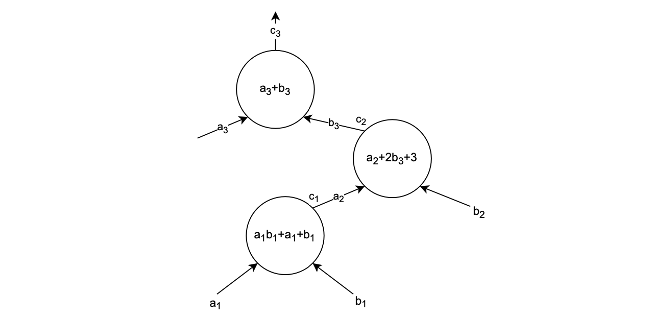
Below figure depicts a \(\mathcal{PlonK}\) circuit.

Observations
-
All values in the below execution trace, depend only on the shape of the circuit itself. So, if the circuit does not change, the corresponding polynomial should not be recomputed.
-
The polynomials; \(\texttt{SA}\), \(\texttt{SB}\) and \(\texttt{SC}\); are constructed so as to enable verification of the copy-constraints; \(c_2 = b_3\) and \(c_1 = a_2\); as shown in the circuit.
-
As explained before, in the construction of the connection \(S\) polynomials, values in cells of the same colour are swapped.
Belo figure shows the execution trace raised by the circuit.

PIL code
The PIL code that validates this circuit is as follows:
include "config.pil";

namespace Plonk(%N);
pol constant QL, QR, QM, QO, QC;
pol constant SA, SB, SC;
pol constant L1;

pol commit a, b, c;

public pi = a(0);

// Public values check
L1 * (a - :pi) = 0;

// Plonk equation
pol ab = a*b;
QL*a + QR*b + QM*ab + QO*c + QC = 0;

// Copy-constraints check
{a, b, c} connect {SA, SB, SC};